- Number of global clocks in each clock region is at most 24 clocks.
- Within each clock region, each half column has at most 12 clocks.
- Each clock region has enough resources to accommodate all clock loads assigned to that region.
- All loads of each clock should be constrained to a rectangular area consisting of one or more clock regions.
Note: for any clock region in this rectangular area, this clock is counted as one of 24 clock usages (Rule 1), even there is no load in this clock region
Please refer to the design.scl that was released along with the
sample benchmark, for a better idea of the resources available for
placement.
Here's the relevant snippet on Slice:
SITE SLICE
  LUT 16
  FF 16
  CARRY8 1
END SITE
Every Slice in the UltraScale architecture contains 16 LUTs and 16 FFs.
-
LUT Packing
Please keep in mind that these 16 LUTs within SLICE are
conceptual LUTs that can only be fully used under certain conditions:
- If you're implementing a 6-input LUT with one output, you can only
use LUT 1 (leaving LUT 0 unused) or LUT 3 (leaving LUT 2 unused) or ...
or LUT 15 (leaving LUT 14 unused)
- If you're implementing two 5-input LUTs with separate outputs but
common inputs, you can use {LUT 0, LUT 1} or {LUT 2, LUT 3} or ... or
{LUT 14, LUT 15}
- The above rule of coming LUTs with separate outputs but common
inputs, holds good for 5-input LUTs (as mentioned above) or fewer input
LUTs as well
- If you're implementing two 3-input (or fewer input) LUTs together
(irrespective of common inputs), you can use {LUT 0, LUT 1} or {LUT 2,
LUT 3} or ... or {LUT 14, LUT 15}
-
FF Packing
There are 16 FFs per SLICE (two per LUT pair), and all can be used fully under certain conditions:
- All FFs can take independent inputs from outside the SLICE, or
outputs of their corresponding LUT pair (FF 0 can take LUT 0 or LUT 1
output as input, ..., FF 15 can take LUT 14 or LUT 15 output as input)
- All can be configured as either edge-triggered D-type flip-flops
or level-sensitive latches. The latch option is by top or bottom half of
the SLICE (0 to 7, and 8 to 15). If the latch option is selected on a
FF, all eight FFs in that half must be either used as latches or left
unused. When configured as a latch, the latch is transparent when the
clock input (CLK) is High.
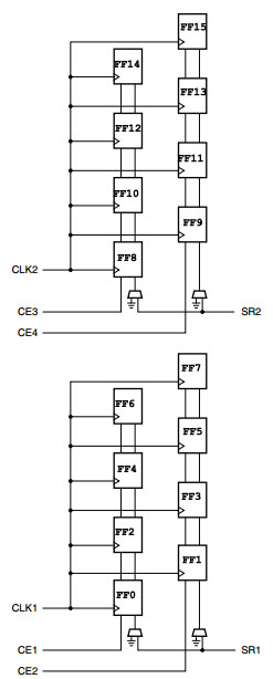
- There are two clock inputs (CLK) and two set/reset inputs (SR) to
every SLICE for the FFs. Each clock or set/reset input is dedicated to
eight of the sixteen FFs, split by top and bottom halves (0 to 7, and 8
to 15). FF pairs ({0,1} or {2,3} or ... or {14,15}) share the same clock
and set/reset signals. The clock and set/reset signals have
programmable polarity at their slice inputs, allowing any inversion to
be automatically absorbed into the CLB.
- There are four clock enables (CE) per SLICE. The clock enables are
split both by top and bottom halves, and by the two FFs per LUT-pair.
Thus, the CEs are independent for: {FF 0, FF 2, FF 4, FF 6} , {FF 1, FF
3, FF 5, FF 7} , {FF 8, FF 10, FF 12, FF 14} , {FF 9, FF 11, FF 13, FF
15}. When one storage element has CE enabled, the other three storage
elements in the group must also have CE enabled. The CE is always active
High at the slice, but can be inverted in the source logic.
For FFs without any net connections to CE pin, vivado software automatically inserts a constant 1, so please do not combine them up with other FFs that have their CE pins connected
- The two SR set/reset inputs to a SLICE can be programmed to be
synchronous or asynchronous. The set/reset signal can be programmed to
be a set or reset, but not both, for any individual FF. The
configuration options for the SR set and reset functionality of a
register or latch are: No set or reset, Synchronous set (FDSE
primitive), Synchronous reset (FDRE primitive), Asynchronous set
(preset) (FDPE primitive), Asynchronous reset (clear) (FDCE primitive).
The SR set/reset input can be ignored for groups of four flip-flops (the
same groups as controlled by the CE inputs). When one FF has SR
enabled, the other three FFs in the group must also have SR enabled.
- The choice of set or reset can be controlled individually for each
FF in a SLICE. The choice of synchronous (SYNC) or asynchronous (ASYNC)
set/reset (SYNC_ATTR) is controlled in groups of eight FFs,
individually for the two separate SR inputs.
Some of the FF Packing rules are better illustrated in the figure below:
More detailed information on Slice Packing & Legalization can be found online at:
http://www.xilinx.com/support/documentation/user_guides/ug574-ultrascale-clb.pdf